Functionality

Conventional heat pipes – evaporation and condensation

Fig. 1: Schematic sketch of a heat pipe

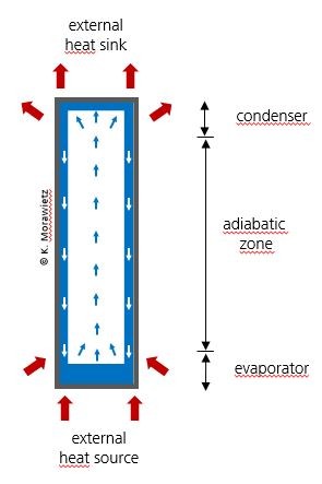
Heat pipes are components that can transfer heat via an evaporation and condensation circuit. When heat is applied to one end of the heat pipe, a working fluid evaporates and flows along the adiabatic zone to the condenser, driven by the temperature or pressure gradient. At the condenser, the vapor condenses and releases its latent heat to an external heat sink

To maintain the cycle, the condensate must be fed back to the evaporator. For this purpose, an integrated wick structure (e.g. groove, mesh or sinter structures) is usually used to transport the condensate back to the evaporator using capillary force. If the condenser is located above the evaporator, gravity can also be used for the return transport. This is called a two-phase thermosiphon. The use of other forces, such as centrifugal forces, is also conceivable for the return of the working fluid.

The working fluid used depends on the temperature range in which the heat pipe is to be used. The most common applications are in the range of approx. -100 to 300 °C. Fluids such as ethanol, acetone or water are typically used here.

Thermal resistance

Heat pipes are characterized by their thermal resistance RHP or thermal conductance UHP. These values are defined as the quotient of the temperature gradient along the heat pipe ΔTHP and the transferred power WHP.

RHP = 1/UHP  = ΔTHP /WHP

The thermal resistance of heat pipes is by orders of magnitude smaller compared to that of a solid metal body with the same dimensions and depends on the operating point (Figure 2).

The maximum possible working range of a heat pipe is between the melting point and the critical point of the selected working fluid. Various physical phenomena influence and limit the performance of heat pipes. These include the viscosity of the fluid, flow velocity in the pipe, shear forces, etc.

In order to optimally operate a heat pipe in a specific application, knowledge, careful consideration and appropriate design are indispensable so that the performance limits are not reached during operation. At the same time, these performance limits can also be exploited to achieve a protective effect, such as preventing the heat sink from overheating.

We will be happy to consult you on these aspects as part of the services we offer.

© Fraunhofer IPM
Fig. 2: Thermal resistance of a self-made, cylindrical heat pipe vs. heat load in comparison with a copper pipe of the same size

Performance limits

Viscosity limit:
At temperatures just above the melting temperature, the viscosity of the fluid is highest and limits the fluid flow and thus the performance of the heat pipe.

Sound velocity limit:
When the steam flow at the evaporator reaches the speed of sound, the sound velocity limit is reached. Then the heat transfer capability of the heat pipe cannot be further increased by pressure reduction in the condenser.

Entrainment limit:
When the entrainment limit is reached, the performance of the heat pipe is limited by shear forces at the phase interface between the rising steam and the returning condensate. The steam flowing at high velocity entrains the returning condensate. This leads to a buildup of condensate within the transport zone, flooding of the condenser and drying out of the evaporator area.

Capillary limit:
In a heat pipe with wick structure, the capillary pressure difference must counteract the sum of all pressure drops along the fluid flow. If the capillary pressure difference is not sufficient to counteract the sum of all pressure drops, not enough condensate will be transported back to the evaporator and the performance of the heat pipe will deteriorate strongly.

Boiling limit:
Nucleate boiling can occur in the evaporator at high heat flux densities. In heat pipes with capillary structures such as sintered metals or meshes, the growing bubbles displace the liquid, condensate reflux is impeded and the capillary structure can dry out locally.

Dryout limit:
In heat pipes that transport the condensate back to the evaporator by means of gravity, the condensate is no longer sufficient to completely wet the evaporator above a certain power and temperature. In extreme cases, the entire working fluid is present in vapor form, so that no more power can be transferred through the evaporation/condensation circuit.

© Fraunhofer IPM
Fig. 3: Various physical phenomena affect and limit the performance of heat pipes. Understanding and considering these effects is a prerequisite to optimally operate a heat pipe in a given application.

Pulsating heat pipes – always on the move

Pulsating heat pipes (PHP) can be used to effectively solve many heat dissipation problems. The PHP can be designed as a bent tube or as a flat plate. While standard heat pipes usually require a wick structure to return the fluid to the heat source, a pulsating heat pipe consists of up to several dozen thin, meandering channels that are partially filled with liquid and evacuated. Due to the surface tension, coherent segments of fluid and steam are formed. The vapor segments expand on the hot side and shrink or condense again on the cold side. As a result, local temperature and pressure differences are always present in the PHP, and the two-phase system strives to compensate for these by applying shifting forces to the fluid/steam segments. These forces generate a constant pulsating movement of the segments such that the system never reaches a static equilibrium. The movement of the segments causes fluid transport from the hot side (heat source) to the cold side and thus also heat transport.

Pulsatin heat pipe
© Fraunhofer IPM
Fig. 4: Operating principle of a pulsating heat pipe
© Fraunhofer IPM
Fig. 5: Thermographic image of a pulsating heat pipe (PHP) made of meandering glass tubes immersed in a hot liquid. Compared to a solid copper rod (left in the image), temperature equalization with a hot liquid occurs very quickly throughout the volume.
© Fraunhofer IPM
Fig. 6: Base plate of a PHP with milled channels. After soldering the base plate to the lid and filling with the fluid, the PHP is ready for use.

Performance data

Pulsating heat pipes can be used as heat spreaders and highly efficient heat flow carriers in air or water cooling. They are therefore ideally suited for cooling electrical components with high heat loads. The thermal resistance of the PHP and consequently the temperature to which the electrical component heats up depend on the boundary conditions. Among other things, the following factors play a role:

  • Structure and dimension of the PHP, e.g. the inner channel structure
  • Working fluid used
  • Size and placement of the component
  • Size and placement of the coupled heat sink

The PHP can be customized for different applications.

Figures 7 and 8 show performance data for a PHP developed at Fraunhofer IPM made of copper with dimensions of just 100 × 50 × 2.5 mm3. The heater – which has an area of 8 × 50 mm² – represents a heating electronic component. Compared to a copper plate with the same dimensions, much lower thermal resistances can be achieved. Electrical components that are cooled with a PHP instead of a copper plate therefore heat up much less.

The critical component temperature (typically 80 – 90 °C) is only reached at a heat output that is higher by a factor of three. For higher heat outputs, the advantage of a PHP over a copper plate of the same size becomes even greater.

The possible maximum thermal power densities of the components are high: in tests, the PHP was able to handle thermal power densities of 50 – 70 W/cm² without any problems – with thermal power densities of > 100 W/cm² being realistic.

Thermal resistance of a PHP
© Fraunhofer IPM
Fig. 7: Thermal resistance of a PHP in vertical operation for different heat flows (blue measuring points). Compared with a plate of the same size made of solid copper (black dashed line), over 80 percent lower thermal resistances can be achieved.
Temperature of a hot component
© Fraunhofer IPM
Fig. 8: Temperature of a hot component for different heat loads

PHP in action

A PHP, made of glass tubing and with water as the working fluid, is immersed in hot water. Immediately, due to the temperature gradient, a fast pulsating movement of the fluid segments starts and thus the heat transport.